This is part 3 of the following series:

  1. Originating requirements
  2. Use cases
  3. Product requirements specification (this document)
  4. Logical and physical architecture

The document refines the high-level requirements into system-level specifications. To contribute more contents, analyze and elaborate further the constraints, performances, and behaviors by the domain-specific knowledge (Mechanical / Electrical / Optical / Software). More importantly, suggest verification plans to test each one.

How to use this document

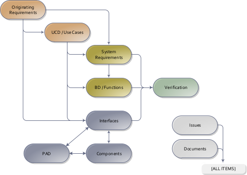
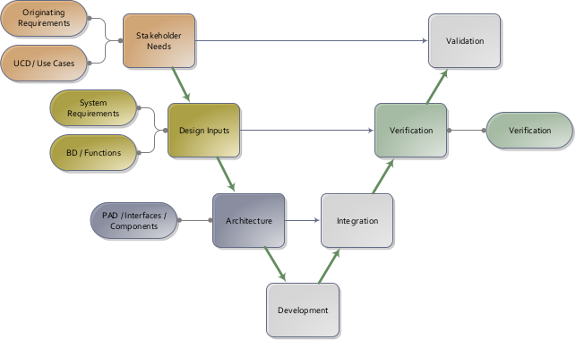
The document refines and analyzes the system-level requirements. Since good system-level requirements aren’t complete unless they are testable, verification is also planned. The goal of this phase is to provide the engineering team with the inputs they need to architect the product.

System engineering V-model. System Requirements refine and internalize the stakeholder needs in the engineering level, and in turn can be verified by Verification Plans.

This is communicated via a Product Requirements Specification (PRS). For ease of review, the PRS has been divided into three separate parts – the Constraint Specification, the Functional Specification, and the Verification Plan. A note on nomenclature – ‘system-level requirements’ are captured in the constraints specification items and in the Behavior Diagrams/functions of the Functional Specifications.

The Constraint Specification contains constraints on the system such as physical characteristics and the environment. The Functional Specification includes the behavior and performance requirements. The Verification Plan contains high level test planning, and traceability back to the system level requirements.

Documents are generated on-demand from a central System Model Database. The contents of Product Requirement and Specifications (PRS) are gathered from the system-level requirements and verifications plans. All chapters can be traced back to the Originating requirements.

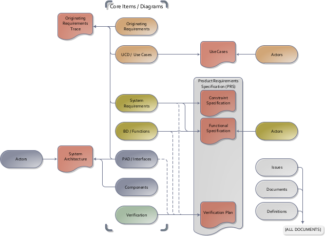
The main items used in this Constraint/Functional specification phase trace from the use cases developed in the previous phase. Walking through the use cases step by step is a systematic method to decompose the relevant requirements.

The verification item is used to plan verification activities at a high level. This allows the stakeholders and engineers to agree on the depth and complexity of testing required. Knowing this, testing schedules, cost, and equipment can be planned, and detailed test procedures written.

System requirements and functions are decomposed from the use cases, which in turn is verified by the Verification plans

Constraint specifications

Charging

sys-1: Charge duration

  • Allocation: ee
  • Discipline: ee
A battery with <5% capacity shall charge to >95% capacity in <5 hours.

Satisfies:

    Designs directly impacted by this:

    • [fnc-1.1] Charge device: The device battery shall charge....
    • [int-1] Power interface: The device connects to a power supply via a connector for charging....

    Verification plans:

    • [ver-1] Re-charging: 1. Connect a device with a low battery to the charger. 1. Confirm charge completes within the specified time limit. 1. Confirm the displays per the diagram. 1. Connect a device with a low battery to the charger. 1. Disconnect the battery prior to th...

    sys-2: Charge indicator location

    • Allocation: user_interface
    • Discipline: mech ee
    The charge indicator shall be located 1.0 +/- 0.2 cm from the charging port.

    Satisfies:

    • [ucd-1] Charging: The device battery is re-charged....

    Designs directly impacted by this:

    • [fnc-1.1] Charge device: The device battery shall charge....
    • [int-2] Front panel: The device has a physical port on the front panel for charging....

    Verification plans:

    • [ver-1] Re-charging: 1. Connect a device with a low battery to the charger. 1. Confirm charge completes within the specified time limit. 1. Confirm the displays per the diagram. 1. Connect a device with a low battery to the charger. 1. Disconnect the battery prior to th...

    Functional specifications

    fnc-1: Charge device

    Charge device
    Connect device to chargerDevice disconnected from charger?no[fnc-1.1] Charge deviceBlink charge indicator yellowCharge complete?noCharge indicator greenyesyes
    Activity diagram "fnc-1: Charge device"

    fnc-1.1: Charge device

    The device battery shall charge.

    Linked requirements:

    • [sys-1] Charge duration: A battery with <5% capacity shall charge to >95% capacity in <5 hours....
    • [sys-2] Charge indicator location: The charge indicator shall be located 1.0 +/- 0.2 cm from the charging port....

    Verification plan

    ver-1: Re-charging

    1. Connect a device with a low battery to the charger. 1. Confirm charge completes within the specified time limit. 1. Confirm the displays per the diagram. 1. Connect a device with a low battery to the charger. 1. Disconnect the battery prior to the battery completely charging. 1. Confirm the displays per the diagram.

    Linked requirements: