How to use this document
This document follows the Product Requirement Specifications (PRS), where the interfaces linking various sub-systems are captured.
There are also lower level internal interfaces; these are often the interfaces that are owned by a single engineer (e.g. the electrical interfaces found on a single circuit board). These lower level interfaces are not given a number and description, are not turned into requirements, and instead are captured in lower level specifications and design documentation.
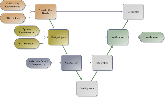
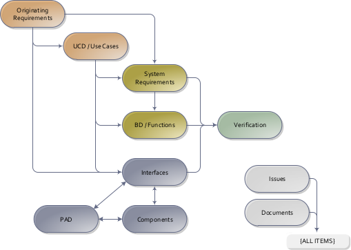
Similar to defining use cases, the process of capturing the architecture via a Physical Architectual Diagram is helpful to ensure that the interfaces are identified. For particularly complicated interfaces, the descriptions above can reference a more detailed document (such as a mechanical interface drawing, electrical pinout, firmware/software communication protocol, etc.).
The Logical Architecture Diagram (LAD) groups the functions into sub-systems. Flows among functions are mapped to Interfaces, featuring interactions among sub-systems. The LAD is in turn implemented by physical components in the Physical Architecture Diagram (PAD). The PAD links all external interfaces with the corresponding internal components of the system.