The document refines the high-level requirements into system-level specifications.
To contribute more contents, analyze and elaborate further the constraints, performances, and behaviors
by the domain-specific knowledge (Mechanical / Electrical / Optical / Software).
More importantly, suggest verification plans to test each one.
How to use this document
The document refines and analyzes the system-level requirements.
Since good system-level requirements aren’t complete unless they are testable,
verification is also planned. The goal of this phase is to provide the engineering team with the
inputs they need to architect the product.
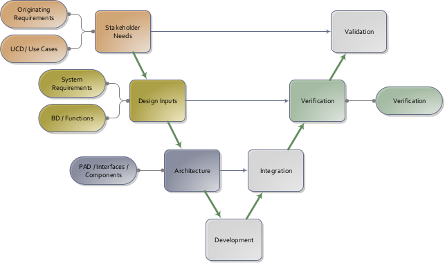
System engineering V-model.
System Requirements refine and internalize the stakeholder needs in the engineering level,
and in turn can be verified by Verification Plans.
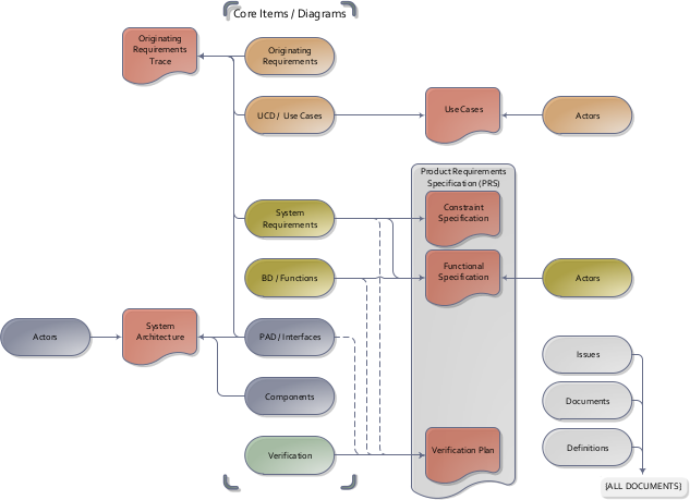
This is communicated via a Product Requirements Specification (PRS).
For ease of review, the PRS has been divided into three separate parts – the
Constraint Specification, the Functional Specification, and the Verification Plan.
A note on nomenclature – ‘system-level requirements’ are captured in the constraints specification items
and in the Behavior Diagrams/functions of the Functional Specifications.
The Constraint Specification contains constraints on the system such as physical characteristics and
the environment.
The Functional Specification includes the behavior and performance requirements.
The Verification Plan contains high level test planning, and traceability back to the system level
requirements.
Documents are generated on-demand from a central System Model Database.
The contents of Product Requirement and Specifications (PRS) are gathered from
the system-level requirements and verifications plans.
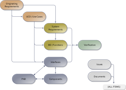
All chapters can be traced back to the Originating requirements.
The main items used in this Constraint/Functional specification phase trace from the use cases developed in the previous phase.
Walking through the use cases step by step is a systematic method to decompose the relevant
requirements.
The verification item is used to plan verification activities at a high level. This allows the
stakeholders and engineers to agree on the depth and complexity of testing required. Knowing this,
testing schedules, cost, and equipment can be planned, and detailed test procedures written.
System requirements and functions are decomposed from the use cases,
which in turn is verified by the Verification plans
Constraint specifications
Alarm
sys-2: Maintain current time and display
Allocation: sw
Discipline: sw ee
The clock radio SHALL accept current time input, maintain the current timestamp, and provide a timestamp display to the user.
Rationale: The user needs to set the correct time and later read it back from the device display.
Satisfies:
[ucd-2]
Get time: The user sets or reads the current time from the clock radio....
Designs directly impacted by this:
[fnc-2.1]
Set current time: The user-facing clock setting function provides the current time input....
[fnc-2.2]
Provide current time settings: The HMI propagates current time settings to the clock logic....
[fnc-2.3]
Clock timestamp: The clock maintains the internal timestamp....
[fnc-2.4]
Display time: The display path converts the maintained timestamp into user-visible output....
[ver-2]
Verify current time maintenance and display: 1. Set the current time through the user interface. 1. Confirm the maintained timestamp updates to the requested time. 1. Confirm the displayed timestamp presented to the user matches the maintained timestamp. ...
Verification plans:
[ver-2]
Verify current time maintenance and display: 1. Set the current time through the user interface. 1. Confirm the maintained timestamp updates to the requested time. 1. Confirm the displayed timestamp presented to the user matches the maintained timestamp. ...
sys-3: Accept alarm settings
Allocation: sw
Discipline: sw ee
The clock radio SHALL accept alarm time and alarm on or off settings from the user and derive current alarm time and alarm activation data for alarm management.
Rationale: The user needs to decide whether wake-up is enabled and when it should occur.
Satisfies:
[ucd-1]
Trigger an alarm: The clock radio wakes the user at the configured alarm time....
Designs directly impacted by this:
[fnc-3.1]
Set alarm time: The user-facing alarm setting function provides alarm time and alarm activation selection....
[fnc-3.2]
Provide alarm settings: The HMI derives current alarm time and alarm activation data for the alarm manager....
[ver-3]
Verify automatic alarm behavior: 1. Enable the alarm, set an alarm time, and place the radio in `Radio AUTO` mode. 1. Operate the clock until current time equals alarm time. 1. Confirm the alarm is triggered at that moment. 1. Continue operating the device and confirm the ringing s...
[int-1]
Alarm time input: The user enters the alarm time and enables or disables the alarm....
Verification plans:
[ver-3]
Verify automatic alarm behavior: 1. Enable the alarm, set an alarm time, and place the radio in `Radio AUTO` mode. 1. Operate the clock until current time equals alarm time. 1. Confirm the alarm is triggered at that moment. 1. Continue operating the device and confirm the ringing s...
Clock
sys-1: Timestamp data type
Allocation: sw
Discipline: sw ee
The clock radio SHALL represent time as a timestamp containing an hour in the range 0 to 23 and a minute in the range 0 to 59.
Rationale: The user expects the device to store current time and alarm time in a normal daily clock format that is unambiguous for display and alarm triggering.
Satisfies:
[ucd-1]
Trigger an alarm: The clock radio wakes the user at the configured alarm time....
[ucd-2]
Get time: The user sets or reads the current time from the clock radio....
Designs directly impacted by this:
[fnc-2.3]
Clock timestamp: The clock maintains the internal timestamp....
[ver-1]
Verify timestamp representation: 1. Review the maintained timestamp data structure in the implementation. 1. Confirm the timestamp contains hour and minute fields. 1. Confirm hour is constrained to 0 through 23 and minute is constrained to 0 through 59. ...
Verification plans:
[ver-1]
Verify timestamp representation: 1. Review the maintained timestamp data structure in the implementation. 1. Confirm the timestamp contains hour and minute fields. 1. Confirm hour is constrained to 0 through 23 and minute is constrained to 0 through 59. ...
Radio
sys-4: Trigger alarm in automatic mode
Allocation: sw
Discipline: sw ee
The clock radio SHALL trigger an alarm when the current time equals the configured alarm time while the system is in `Radio AUTO` mode.
Rationale: The automatic mode exists so the device can remain quiet until the scheduled wake-up condition occurs.
Satisfies:
[ucd-1]
Trigger an alarm: The clock radio wakes the user at the configured alarm time....
[org-4]
Support radio modes: The clock radio SHALL support explicit radio operating modes so the user can keep radio playback on, off, or automatically driven by the alarm. ...
Designs directly impacted by this:
[fnc-3.3]
Trigger alarm: The alarm manager triggers the alarm when timestamp and alarm conditions are satisfied....
[ver-3]
Verify automatic alarm behavior: 1. Enable the alarm, set an alarm time, and place the radio in `Radio AUTO` mode. 1. Operate the clock until current time equals alarm time. 1. Confirm the alarm is triggered at that moment. 1. Continue operating the device and confirm the ringing s...
[int-4]
Clock signal: The clock provides timing information to the alarm controller....
[int-5]
Alarm signal: The alarm controller provides an alarm trigger to the speaker path....
Verification plans:
[ver-3]
Verify automatic alarm behavior: 1. Enable the alarm, set an alarm time, and place the radio in `Radio AUTO` mode. 1. Operate the clock until current time equals alarm time. 1. Confirm the alarm is triggered at that moment. 1. Continue operating the device and confirm the ringing s...
sys-5: Limit automatic ringing duration
Allocation: sw
Discipline: sw ee
In `Radio AUTO` mode, the ringing state SHALL return to silent after an alarm timeout of 59 minutes.
Rationale: The wake-up function should not leave the device ringing indefinitely after the alarm has been triggered.
Satisfies:
[ucd-1]
Trigger an alarm: The clock radio wakes the user at the configured alarm time....
[org-4]
Support radio modes: The clock radio SHALL support explicit radio operating modes so the user can keep radio playback on, off, or automatically driven by the alarm. ...
Designs directly impacted by this:
[fnc-3.3]
Trigger alarm: The alarm manager triggers the alarm when timestamp and alarm conditions are satisfied....
[ver-3]
Verify automatic alarm behavior: 1. Enable the alarm, set an alarm time, and place the radio in `Radio AUTO` mode. 1. Operate the clock until current time equals alarm time. 1. Confirm the alarm is triggered at that moment. 1. Continue operating the device and confirm the ringing s...
[int-5]
Alarm signal: The alarm controller provides an alarm trigger to the speaker path....
Verification plans:
[ver-3]
Verify automatic alarm behavior: 1. Enable the alarm, set an alarm time, and place the radio in `Radio AUTO` mode. 1. Operate the clock until current time equals alarm time. 1. Confirm the alarm is triggered at that moment. 1. Continue operating the device and confirm the ringing s...
sys-7: Decode radio waves
Allocation: sw
Discipline: sw ee
The clock radio SHALL receive radio waves from the external transmitter and decode them into radio signals using the current frequency setting.
Rationale: The user expects the device to transform incoming radio transmission into an internal signal usable for playback.
Satisfies:
[ucd-3]
Get news: The user configures the radio and listens to received radio audio....
Designs directly impacted by this:
[fnc-4.4]
Decode radio waves: The radio MMI decodes incoming radio waves into radio signals....
[ver-4]
Verify radio setting, decode, and playback path: 1. Set radio frequency, volume, and radio on or off selection through the user interface. 1. Provide a usable radio transmission to the device. 1. Confirm the device derives current frequency, activation, and volume level from the user settings. 1. ...
[int-3]
Radio channel input: The external transmitter provides a radio channel to the clock radio receiver....
[int-6]
Audio signal: The radio demodulator provides decoded audio to the speaker path....
Verification plans:
[ver-4]
Verify radio setting, decode, and playback path: 1. Set radio frequency, volume, and radio on or off selection through the user interface. 1. Provide a usable radio transmission to the device. 1. Confirm the device derives current frequency, activation, and volume level from the user settings. 1. ...
sys-8: Broadcast radio sound
Allocation: sw
Discipline: sw ee
The clock radio SHALL broadcast radio sound to the user from radio signals, alarm input, activation, and volume level.
Rationale: The radio path and the alarm path both exist to produce audible output that the user can hear.
Satisfies:
[ucd-1]
Trigger an alarm: The clock radio wakes the user at the configured alarm time....
[ucd-3]
Get news: The user configures the radio and listens to received radio audio....
Designs directly impacted by this:
[fnc-4.5]
Broadcast radio: The radio component combines alarm, activation, radio signal, and volume inputs into radio sound....
[ver-4]
Verify radio setting, decode, and playback path: 1. Set radio frequency, volume, and radio on or off selection through the user interface. 1. Provide a usable radio transmission to the device. 1. Confirm the device derives current frequency, activation, and volume level from the user settings. 1. ...
[int-2]
Audio output: The clock radio provides audible output to the user....
[int-5]
Alarm signal: The alarm controller provides an alarm trigger to the speaker path....
[int-6]
Audio signal: The radio demodulator provides decoded audio to the speaker path....
Verification plans:
[ver-4]
Verify radio setting, decode, and playback path: 1. Set radio frequency, volume, and radio on or off selection through the user interface. 1. Provide a usable radio transmission to the device. 1. Confirm the device derives current frequency, activation, and volume level from the user settings. 1. ...
sys-9: Support radio operating modes
Allocation: sw
Discipline: sw ee
The clock radio SHALL support the operating modes `Radio OFF`, `Radio ON`, and `Radio AUTO`, with transitions triggered by the `radio off`, `radio on`, and `radio auto` events.
Rationale: The owner wants explicit user-selectable radio behavior rather than a single fixed playback mode.
Satisfies:
[ucd-1]
Trigger an alarm: The clock radio wakes the user at the configured alarm time....
[ucd-3]
Get news: The user configures the radio and listens to received radio audio....
[org-4]
Support radio modes: The clock radio SHALL support explicit radio operating modes so the user can keep radio playback on, off, or automatically driven by the alarm. ...
Designs directly impacted by this:
[fnc-4.2]
Listen to radio: The user consumes radio sound and controls radio mode selection....
[fnc-4.3]
Provide radio settings: The HMI derives activation, current frequency, and volume level for the radio path....
[ver-5]
Verify radio operating modes: 1. Initialize the device and confirm the default radio mode is `Radio OFF`. 1. Trigger `radio on` and confirm the system enters `Radio ON`. 1. Trigger `radio auto` and confirm the system enters `Radio AUTO`. 1. Trigger `radio off` from `Radio ON` an...
Verification plans:
[ver-5]
Verify radio operating modes: 1. Initialize the device and confirm the default radio mode is `Radio OFF`. 1. Trigger `radio on` and confirm the system enters `Radio ON`. 1. Trigger `radio auto` and confirm the system enters `Radio AUTO`. 1. Trigger `radio off` from `Radio ON` an...
UserInterface
sys-6: Accept radio settings
Allocation: sw
Discipline: sw ee
The clock radio SHALL accept radio on or off mode selection, frequency, and volume settings from the user and derive activation, current frequency, and volume level data for radio playback.
Rationale: The user needs direct control over whether radio playback is active and how it should be tuned and heard.
Satisfies:
[ucd-1]
Trigger an alarm: The clock radio wakes the user at the configured alarm time....
[ucd-3]
Get news: The user configures the radio and listens to received radio audio....
[org-4]
Support radio modes: The clock radio SHALL support explicit radio operating modes so the user can keep radio playback on, off, or automatically driven by the alarm. ...
Designs directly impacted by this:
[fnc-4.1]
Set radio: The user-facing radio setting function provides tuning and volume input....
[fnc-4.2]
Listen to radio: The user consumes radio sound and controls radio mode selection....
[fnc-4.3]
Provide radio settings: The HMI derives activation, current frequency, and volume level for the radio path....
[ver-4]
Verify radio setting, decode, and playback path: 1. Set radio frequency, volume, and radio on or off selection through the user interface. 1. Provide a usable radio transmission to the device. 1. Confirm the device derives current frequency, activation, and volume level from the user settings. 1. ...
Verification plans:
[ver-4]
Verify radio setting, decode, and playback path: 1. Set radio frequency, volume, and radio on or off selection through the user interface. 1. Provide a usable radio transmission to the device. 1. Confirm the device derives current frequency, activation, and volume level from the user settings. 1. ...
Functional specifications
fnc-1: Operate clock radio
Operate the clock, alarm, and radio functions needed by the clock radio, using the logical functions identified in the Capella source model.
Flow diagram "fnc-1: Operate clock radio"
fnc-1.0: Clock radio functional flow
Coordinate the clock, alarm, and radio sub-behaviors for end-to-end clock radio operation.
Linked requirements:
fnc-2: Manage clock
Provide current time settings, maintain the current timestamp, and display the current time to the user.
Flow diagram "fnc-2: Manage clock"
fnc-2.1: Set current time
The user-facing clock setting function provides the current time input.
Linked requirements:
[sys-2]
Maintain current time and display: The clock radio SHALL accept current time input, maintain the current timestamp, and provide a timestamp display to the user....
fnc-2.2: Provide current time settings
The HMI propagates current time settings to the clock logic.
Linked requirements:
[sys-2]
Maintain current time and display: The clock radio SHALL accept current time input, maintain the current timestamp, and provide a timestamp display to the user....
fnc-2.3: Clock timestamp
The clock maintains the internal timestamp.
Linked requirements:
[sys-1]
Timestamp data type: The clock radio SHALL represent time as a timestamp containing an hour in the range 0 to 23 and a minute in the range 0 to 59....
[sys-2]
Maintain current time and display: The clock radio SHALL accept current time input, maintain the current timestamp, and provide a timestamp display to the user....
fnc-2.4: Display time
The display path converts the maintained timestamp into user-visible output.
Linked requirements:
[sys-2]
Maintain current time and display: The clock radio SHALL accept current time input, maintain the current timestamp, and provide a timestamp display to the user....
fnc-3: Manage alarm
Capture alarm settings, derive current alarm data, and trigger the alarm when the current timestamp reaches the configured alarm time in automatic mode.
Flow diagram "fnc-3: Manage alarm"
fnc-3.1: Set alarm time
The user-facing alarm setting function provides alarm time and alarm activation selection.
Linked requirements:
[sys-3]
Accept alarm settings: The clock radio SHALL accept alarm time and alarm on or off settings from the user and derive current alarm time and alarm activation data for alarm management....
fnc-3.2: Provide alarm settings
The HMI derives current alarm time and alarm activation data for the alarm manager.
Linked requirements:
[sys-3]
Accept alarm settings: The clock radio SHALL accept alarm time and alarm on or off settings from the user and derive current alarm time and alarm activation data for alarm management....
fnc-3.3: Trigger alarm
The alarm manager triggers the alarm when timestamp and alarm conditions are satisfied.
Linked requirements:
[sys-4]
Trigger alarm in automatic mode: The clock radio SHALL trigger an alarm when the current time equals the configured alarm time while the system is in `Radio AUTO` mode....
[sys-5]
Limit automatic ringing duration: In `Radio AUTO` mode, the ringing state SHALL return to silent after an alarm timeout of 59 minutes....
fnc-4: Manage radio
Capture radio settings, decode radio waves, manage radio modes, and broadcast radio sound to the user.
Flow diagram "fnc-4: Manage radio"
fnc-4.1: Set radio
The user-facing radio setting function provides tuning and volume input.
Linked requirements:
[sys-6]
Accept radio settings: The clock radio SHALL accept radio on or off mode selection, frequency, and volume settings from the user and derive activation, current frequency, and volume level data for radio playback....
fnc-4.2: Listen to radio
The user consumes radio sound and controls radio mode selection.
Linked requirements:
[sys-6]
Accept radio settings: The clock radio SHALL accept radio on or off mode selection, frequency, and volume settings from the user and derive activation, current frequency, and volume level data for radio playback....
[sys-9]
Support radio operating modes: The clock radio SHALL support the operating modes `Radio OFF`, `Radio ON`, and `Radio AUTO`, with transitions triggered by the `radio off`, `radio on`, and `radio auto` events....
fnc-4.3: Provide radio settings
The HMI derives activation, current frequency, and volume level for the radio path.
Linked requirements:
[sys-6]
Accept radio settings: The clock radio SHALL accept radio on or off mode selection, frequency, and volume settings from the user and derive activation, current frequency, and volume level data for radio playback....
[sys-9]
Support radio operating modes: The clock radio SHALL support the operating modes `Radio OFF`, `Radio ON`, and `Radio AUTO`, with transitions triggered by the `radio off`, `radio on`, and `radio auto` events....
fnc-4.4: Decode radio waves
The radio MMI decodes incoming radio waves into radio signals.
Linked requirements:
[sys-7]
Decode radio waves: The clock radio SHALL receive radio waves from the external transmitter and decode them into radio signals using the current frequency setting....
fnc-4.5: Broadcast radio
The radio component combines alarm, activation, radio signal, and volume inputs into radio sound.
Linked requirements:
[sys-8]
Broadcast radio sound: The clock radio SHALL broadcast radio sound to the user from radio signals, alarm input, activation, and volume level....
Verification plan
ver-1: Verify timestamp representation
Allocation: clock_radio
Discipline: sw ee
1. Review the maintained timestamp data structure in the implementation.
1. Confirm the timestamp contains hour and minute fields.
1. Confirm hour is constrained to 0 through 23 and minute is constrained to 0 through 59.
Linked requirements:
[sys-1]
Timestamp data type: The clock radio SHALL represent time as a timestamp containing an hour in the range 0 to 23 and a minute in the range 0 to 59....
ver-2: Verify current time maintenance and display
Allocation: clock_radio
Discipline: sw ee
1. Set the current time through the user interface.
1. Confirm the maintained timestamp updates to the requested time.
1. Confirm the displayed timestamp presented to the user matches the maintained timestamp.
Linked requirements:
[sys-2]
Maintain current time and display: The clock radio SHALL accept current time input, maintain the current timestamp, and provide a timestamp display to the user....
ver-3: Verify automatic alarm behavior
Allocation: clock_radio
Discipline: sw ee
1. Enable the alarm, set an alarm time, and place the radio in `Radio AUTO` mode.
1. Operate the clock until current time equals alarm time.
1. Confirm the alarm is triggered at that moment.
1. Continue operating the device and confirm the ringing state returns to silent after 59 minutes.
Linked requirements:
[sys-3]
Accept alarm settings: The clock radio SHALL accept alarm time and alarm on or off settings from the user and derive current alarm time and alarm activation data for alarm management....
[sys-4]
Trigger alarm in automatic mode: The clock radio SHALL trigger an alarm when the current time equals the configured alarm time while the system is in `Radio AUTO` mode....
[sys-5]
Limit automatic ringing duration: In `Radio AUTO` mode, the ringing state SHALL return to silent after an alarm timeout of 59 minutes....
ver-4: Verify radio setting, decode, and playback path
Allocation: clock_radio
Discipline: sw ee
1. Set radio frequency, volume, and radio on or off selection through the user interface.
1. Provide a usable radio transmission to the device.
1. Confirm the device derives current frequency, activation, and volume level from the user settings.
1. Confirm the radio subsystem decodes radio waves into radio signals and broadcasts radio sound to the user.
Linked requirements:
[sys-7]
Decode radio waves: The clock radio SHALL receive radio waves from the external transmitter and decode them into radio signals using the current frequency setting....
[sys-8]
Broadcast radio sound: The clock radio SHALL broadcast radio sound to the user from radio signals, alarm input, activation, and volume level....
[sys-6]
Accept radio settings: The clock radio SHALL accept radio on or off mode selection, frequency, and volume settings from the user and derive activation, current frequency, and volume level data for radio playback....
ver-5: Verify radio operating modes
Allocation: clock_radio
Discipline: sw ee
1. Initialize the device and confirm the default radio mode is `Radio OFF`.
1. Trigger `radio on` and confirm the system enters `Radio ON`.
1. Trigger `radio auto` and confirm the system enters `Radio AUTO`.
1. Trigger `radio off` from `Radio ON` and `Radio AUTO` and confirm the system returns to `Radio OFF`.
Linked requirements:
[sys-9]
Support radio operating modes: The clock radio SHALL support the operating modes `Radio OFF`, `Radio ON`, and `Radio AUTO`, with transitions triggered by the `radio off`, `radio on`, and `radio auto` events....