Electronics
Digital circuit and FPGA
Parallel frame grabber with 96 automative CMOS’s for drug discovery
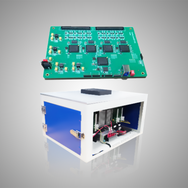
As part of the OEM provided design “ride-share” program, I contracted out the 96-CMOS single-board camera and FPGA-based frame grabber card array design & fabrication. I drafted and negotiated the pixel readout requirements, reviewed circuit schematics, and provided pre-fab feedback on the PCB’s thermal load and EMI. The 96-CMOS subsystem is successfully integrated into the parallel microscope for high-throughput drug discovery at Amgen. The “ride-share” program enables a shared domain knowledge with another customer, which in turn accelerated the completion of similar projects.
Publication: A.C.S. Chan, J Kim, A Pan, H Xu, D Nojima, C Hale, S Wang, C Yang, “Parallel Fourier ptychographic microscopy for high-throughput screening with 96 cameras (96 Eyes)” Scientific Reports 9, 11114 (2019).
Mixed-signal circuit
4-channel Peltier PID cooler for 3.5Watt laser modules, 30W per channel

The custom PCB to control up to 4 individual Peltier coolers interfacing the high power laser modules.
Technical specifications:
Input: 24VDC, max 20A.
Output per channel: up to 10A, PWM at 5% to 100% duty cycle. 30N06L
Recommended Peltier module: series-parallel modules supporting up to 24VDC input, with up to 50W heat transfer on the cold side.
Temperature sensor: Dallas digital temperature sensor with One-Wire interface. DS18B20
Microcontroller (MCU) power supply: 5VDC, max 200mA. Completely separated from the 12DVC supply.
MCU programming interface: UART over TTL, via a 6-pin connector with the FTDI friend USB adapter.
External set point control: I2C bus to reduce the cabling effort.
Project website: https://github.com/antonysigma/peltier-cooler-4ch
Why I made my own board The board is primarily used to dissipate the waste heat from the 3,000mW laser modules. A high laser power is required to compensate the coupling loss of the homogenizing liquid light-guide and the TV lens, so that I can excite the fluorescence-stained mammalian cells on all 96 wells of the multi-well plate (area: 180mm x 90mm).
At the time, there was an urgent need to create an evaluation board at less than 10% of the cost of the OEM laser parts. So, the OEM provided temperature controller evaluation kits were a no-go.
If I had more time on the project, I would have enabled the staggered, phase-correct PWM to minimize the transient current load. Staggered PWM significantly reduces the dead time on the powerline, as well as reduces the EMI noise.
Piezo-flexure nano-positioning stage control board

The PCB to implement z-stack focus scanning with a custom piezo-flexure nano-positioning stage.
Technical specifications:
Power input: 5VDC, max 200mA.
Output: analog output for the piezo class-A amplifier, bandwidth 250kHz max, dual rail +/- 5V via the 50 Ohm coaxial cable.
Position sensor: linear encoder with differential quadrature TTL output.
MCU programming interface: UART over TTL, via a 6-pin connecter with the FTDI friend USB adapter.
External position control: I2C bus to reduce the cabling effort.
Project website: https://github.com/antonysigma/piezo-stage-pid-board
Why I made my own board The board is primarily used to actuate the Piezo-flexure nano-positioning Z-axis stage at a step size of 5 micrometer; full travel range of 0~250 micrometer, and a close-loop settle time of 50 millisecond. The 50 millisecond settle time requirement originates from the need to avoid motion blur in the 96-camera imaging light path; the stage must settle completely before the flurorescence-excitation flash light can be turned on.
Precise spin control of BioDVD imaging platform

With Anson Tang, I built a digital PID controller with ATTiny/AVR chips enabling precise speed control of BioDVD platform for microslide digitization within 5 minutes.
Project website: https://github.com/antonysigma/dvd-spindle-motor-driver
Anson H. L. Tang, P. Yeung, Godfrey C. F. Chan, Barbara P. Chan, Kenneth K. Y. Wong, and Kevin K. Tsia, “Time-stretch microscopy on a DVD for high-throughput imaging cell-based assay,” Biomed. Opt. Express 8, 640–652 (2017)
74HC logic board for synchronous frequency control of the acousto-optic deflector
Line follower robot using pure IC logic for STEM education
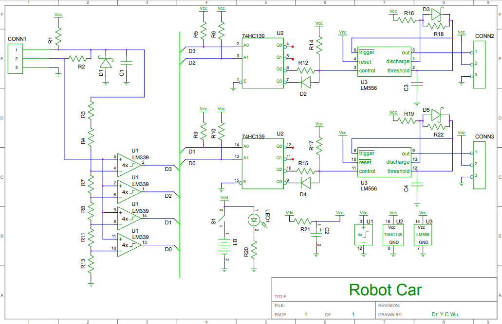
This is a line following car built entirely out of 74HC digital IC logic and LM analog IC logic, with the focus of “form… shall ever follows function”. The following first principles are taught under the disguise of car race:
Optical physics: how one can measure distance, offset, and specular reflectivity with an infrared proximity sensor;
Analog electronics: how one can reduce measurement noise with signal-conditining RC circuits.
Digital signal processing: how one can eliminate electronic component variations by digitizing the proximity sensor inputs. Why digital signals can enable in-circuit programming, as well as design verifications on paper.
Power electronics design: how one can generate a PWM signal from OpAmps to convert the digital control signal to an analog control signal (sigma delta DAC), which in turn is used to drive the parallex motor on the wheels.
Design for manufacturing: how the control board should be built to minimize damage due to shock and vibrations. How one can trade inventory complexity and system robustness when engineers sources for components.
Mechanical engineering: how one can ensure wheel traction as a function of wheel diameter, torque, tire material, and rotation speed.
Close-loop control theory: how one can tune the open-loop gain of the system to increase car speed, while minimizing oscillations and loss of line-tracking during turns, a Pareto-optiminal multi-criteria optimization problem.
Why I make my own board Today’s proliferation of complex embedded electronics has led to a Quadcore CPU-enabled soldering iron, and a line following car running rich Linux operating system. It breaks my heart that these advanced technologies, e.g. Raspberry Pi, FPGA, and Arduino, are made to serve such a humble application. These system-on-boards (SoBs), and system-on-chip (SoCs) exist to solve a more sophisticated problem.
To be fair, these education kits are ideal for student’s exposure to the bleeding edge technologies; depending on where you live, it might help build your resume as a salesperson boosting the component sales of the OEM vendors. The strategy also helps the vendors because of the vendor lock-in and technology inertia built into the education kits. However, they often fall short of teaching the core STEM principle: “form shall ever follows function”. To train an inquiring scientific mind, one should first define what the robot should behave to follow the track based on stakeholder’s needs, not how the robot should execute the program to steer the wheels. In other words, one should build a design first, then map the design to the technology.
Schematic capture and PCB design:
attached/Robot-car.zip
Analog circuit (microwave)
Phase locking of 10MHz femtosecond mode-locked laser
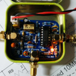
I designed a phase lock loop (PLL) amplifier to generate a 10 MHz TTL signal synchronized to the ultrashort pulsed fiber laser at 400 femtosecond pulse width.
Project website: https://github.com/antonysigma/femptosecond-pulse-trigger-pcb
Details of the ANDi laser that we assembled in house.
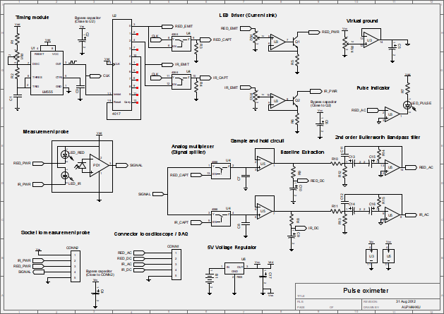
Pulse oximeter signal conditioning circuit for STEM education